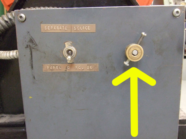
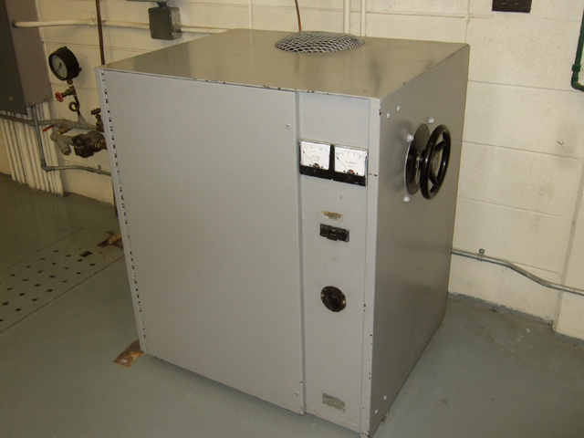
“TEST the overspeed trip” vs. “HIT the overspeed trip”

During SAIT steam lab competencies for turbines, students may be asked to either “TEST the overspeed trip” or “HIT the overspeed trip”.

These are two completely different requests, and it would be a shame to lose marks for not knowing the difference.

I. TEST the overspeed trip

  1. Increase the RPMs gradually, by opening the turbine governor slowly and deliberately.
  2. Watch the RPM indicator, and report to the instructor the final value at which the turbine tripped.
  3. Close the steam inlet valve.

II. HIT the overspeed trip

  1. Push the locking bar on the overspeed trip (for the Coppus turbine) or pull the overspeed trip (on the Bellis & Morcom turbine) to bring the turbine to a stop.
  2. Close the steam inlet valve.

John Inglis Boiler operation

[Special thanks to Instructor Jim Nelson for reviewing this set of procedures and making helpful suggestions.]

Procedures for starting & stopping the John Inglis boiler in SAIT’s power engineering lab. This checklist is currently correct (as of October 18, 2014), but may be subject to change in the future.

Start-up (pre-checks)

  1. Check steam pressure.
    1. If performing a cold start in which boiler pressure is zero, open the air vent. (This will allow air to enter the boiler and relieve any vacuum.)
  2. Check that boiler water level is OK. (If the level is too high, the boiler should be blown down. If too low, more water must be introduced to the boiler.)
  3. Pilot line valve should be OFF.
  4. Main gas valve should be OFF.
  5. Emergency shutoff switch should be not be engaged (ie: the system should be operable).
  6. Forced draft (FD) fan should be ON.
  7. Burner system switch should be ON.

Start-up (Purge)

  1. On right-hand-side (RHS) computer monitor, check that gas flow is ZERO.
  2. On the RHS computer monitor, bring air flow to 100% using the >> icon. A green light on the LHS computer monitor indicates that the furnace purge is in progress.
  3. Watch for the Purge Complete light on the John Inglis panel to turn yellow (alternatively, watch for this indication on the left computer monitor). This should occur after about 1 ½ minutes.
  4. On the RHS computer monitor, quickly bring the air flow to 0% using the << icon.

Start-up

The next few steps are time-dependent, and need to be performed as quickly and efficiently as possible.

  1. Turn the pilot line valve ON.
  2. Watch for the yellow Ignition light on the John Inglis panel to activate.
  3. Look through the furnace glass in the front of the boiler. Check that the pilot flame is ON.
  4. Move to the left side of the boiler and turn the manual solenoid switch OFF.
  5. Listen for actuator clicks. The burner ignition system is opening the gas valves in sequence.
  6. Turn the manual solenoid lever switch ON. (Swing the solenoid lever to the left. You should encounter some resistance from the lever while doing so.)
  7. Move to the front of the boiler, and slowly turn ON the main gas line with the valve wrench. (If this is done too quickly, the rush of gas could extinguish the pilot light). Open fully.
  8. Return the valve wrench to its holder.
  9. Move to the back of the boiler, and check that the main burner is ON.
  10. Move to the front of the boiler, and turn off the pilot light valve.
  11. Check that the water level in the deaerator is adequate. If not:
    1. Check that the zeolite softener lines to the deaerator are CLOSED.
    2. Fast rinse the zeolite softener and the sampling tap for a minute or two.
    3. Rinse the sample casserole and stir stick a few times with water from the zeolite softener.
    4. Take a sample, and test for hardness.
    5. If the sample contains HARD water, regenerate the zeolite softener.
    6. If the sample contains SOFT water, OPEN the zeolite softener lines to the deaerator.
  12. Start the boiler feedwater pump and begin sending boiler feedwater to the boiler by adjusting the drum water level on the RHS computer monitor.
  13. At this point, the operator will need to pressurize the High Pressure Steam header.
  14. If performing a cold start, wait until steam strongly emerges from the vent. Close the vent.

Operation

  1. If performing a cold start, warm the boiler up slowly. This entails running at minimum fire (Gas = 0, Air = 0) until boiler pressure reaches 20 psi. The Air and Gas can then be gradually increased to about 30 each.
  2. When increasing the fire rate, increase Air and Gas in equal amounts – with Air added first, followed by Gas.
  3. When decreasing the fire rate, decrease Air and Gas in equal amounts – with Gas subtracted first, followed by Air.

Shut-down

  1. Turn OFF the main gas valve with the valve wrench. The Burner Off alarm will activate within 15 seconds.
  2. Turn OFF the FD fan switch.
  3. Turn OFF the burner switch.
  4. Wait for the Burner Off alarm.
  5. Hold the red Reset button for 3 seconds to turn off the Burner Off alarm. (Do not hold down continuously, or the Burner Off alarm will continue to sound until the Reset button is released!)
  6. If shutting down for the night:
    1. Shut down the Boiler Feedwater system:
      1. Close the discharge valve of the Feed Water Pump.
      2. Turn OFF the Feed Water Pump.
      3. Close the Feed Water valve at the front of the boiler.
    2. Close outlet valve on zeolite softener.
    3. Climb to the top of the boiler, and close the Screw-Down Non-Return Valve supplying boiler steam to the High Pressure Steam header.
    4. Crack the header drains.
    5. Close the Continuous Blowdown valve, or the boiler will continuously drain water all night long.
    6. Make certain that the Intermittent Blowdown valves are closed, or the boiler will lose water within a very short time.
    7. When High Pressure Steam header is at 0 psi, open all header drains fully.
    8. Turn OFF gauge glass light.

[print-me]

Regulations for ABSA Fourth Class Power Engineering tests

ABSA requires two tests for its 4th Class Power Engineering certificate (Part A & Part B), with each test consisting of 150 questions.

Of these 150 questions, roughly 10 are regulation-related. While test-takers are not required to know the regulations chapter and verse, they are expected to be able to consult them correctly during the exam.

Test candidates are permitted to bring the following regulatory resources into the exam room:

Safety Codes Act: Revised Statutes of Alberta 2000 (Chapter S-1)

Safety Codes Act: Power Engineers Regulation

Safety Codes Act: Pressure Welders Regulation

Safety Codes Act: Pressure Equipment Safety Regulation

In addition, candidates may also use:

  • CSA B-51: Boiler, Pressure Vessel and Pressure Piping Code
  • CSA B-52: Mechanical Refrigeration Code

An extract of these two codes is available from Pan Global for roughly $84.

Those taking the test may highlight and add tabs to these regulations prior to the exam, but are prohibited from writing in them.

(A small number of these resources is usually available in the exam room for common use, but depending on these leaves the candidate at the mercy of everyone else attempting to read them at the same time!)


Postscript: To keep all the pages together, consider getting each of these spirally-bound at a copy shop. It costs about $18 to get the first four sets of regulations bound separately at Staples.


UPDATE (September 29/2014): Other links to the first four materials:

Safety Codes Act: Revised Statutes of Alberta 2000 (Chapter S-1)

Safety Codes Act: Power Engineers Regulation

Safety Codes Act: Pressure Welders Regulation

Safety Codes Act: Pressure Equipment Safety Regulation
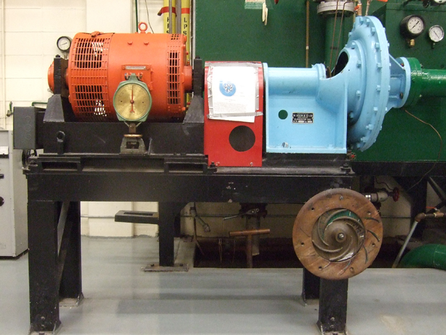
Sisson Centrifugal Pump operation

[Special thanks to Instructor Dale Nelson for reviewing this set of procedures and clearing up some misconceptions I had.]

This post outlines how to start & stop the Sisson Centrifugal Pump setup in SAIT’s power engineering lab.

Photo of Sisson centrifugal pump

Sisson centrifugal pump

These procedures are currently correct (as of October 3, 2014), but may be subject to change in the future.

Preliminaries

  1. Open suction line. (If this is not done, the bronze impeller could be damaged from cavitation.)

    Suction valve

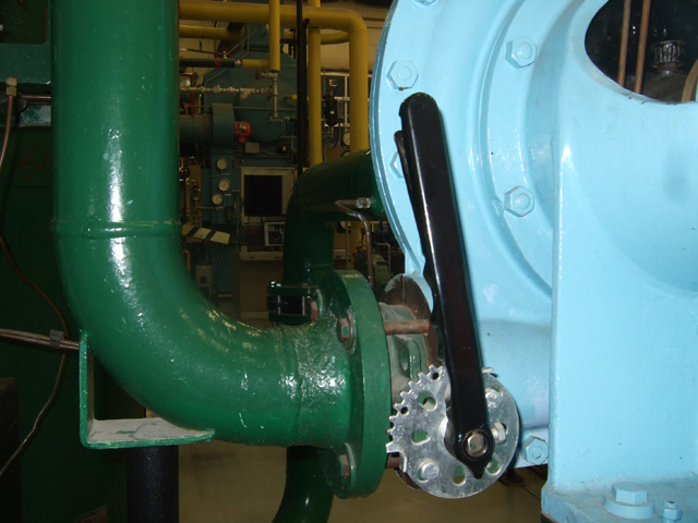
    Ratchet butterfly valve on suction line (shown Open)

  2. Close discharge line.

    Ratchet butterfly valve on discharge line

    Ratchet butterfly valve on discharge line (shown Closed)

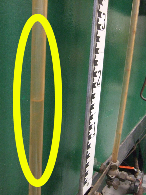
  3. Check sight glass on the receiving tank. (The receiving tank should not be too full, or it could overflow).

    Sight glass (circled in yellow)

    Sight glass (circled in yellow)

  4. Check water level in the source pit. (The pit should be 2/3 – 3/4 full. Fill if necessary by opening the valve on the receiving tank).
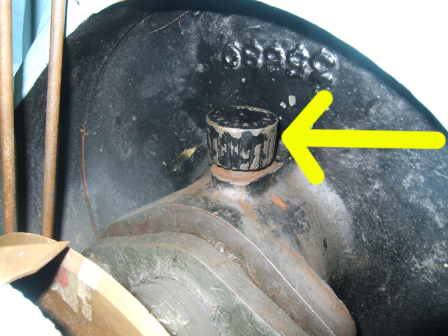
  5. Check pump motor lubrication. (The lubrication nipple should have grease filled to the top). Loosen & tighten cap by hand.

    Lubrication nipple (shown with cap on)

    Lubrication nipple (shown with cap on)

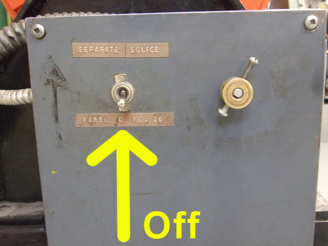
  6. Check that the fan trim switch on the pump casing is Off.

    Fan trim switch

    Fan trim switch

  7. Set long arm of motor trim dial on the pump casing to the 2 o’clock position.

    Trim dial to the 2 o'clock position (this looks more like the 1 o'clock position)

    Trim dial to the 2 o’clock position (although this looks more like the 1 o’clock position!)

  8. Check rectifier:

    DC rectifier

    DC rectifier

    1. Rectifier control switch should be Off.
    2. Rectifier fan should be Off.
    3. Rectifier rheostat should be at 0.
  9. Check that Disconnect #2 switch is Off (ie: in the middle position).
  10. Check that Disconnect #1 (DC Rectifier & Pump switch) is in the 0 (lower) position.
  11. Check fuse box for Fuse #40. The rectifier fuse should be in the On position (flipped to the left).
  12. Prepare to close Disconnect #1 (DC Rectifier & Pump switch):
    1. Stand to the side of the switch panel and do not cross in front of it.
    2. Grip switch with non-dominant hand while looking away.
    3. Take a deep breath and hold breath.
    4. Flip switch DOWN while gripping locking mechanism.
    5. Release locking mechanism.
    6. All this is necessary in case arcing blows door off knife switch case (causing potential eye & hand damage).
  13. Prepare to close Disconnect #2:
    1. Stand to the side of the switch panel and do not cross in front of it.
    2. Grip switch with non-dominant hand while looking away.
    3. Take a deep breath and hold breath.
    4. Disengage locking mechanism and flip switch DOWN.
    5. Release locking mechanism.
  14. Turn on the rectifier fan.
  15. Turn on the rectifier.
  16. Turn on the trim fan switch on the pump casing.
  17. Use back of hand to check if rectifier fan is blowing.

Priming the pump

  1. Turn on small priming water valve slowly.
  2. Open discharge valve slowly.
  3. Open primer air vents until only water emerges from tubes.
  4. Close primer air vents.
  5. Close discharge valve slowly.
  6. Turn off small priming water valve slowly.

Bring pump up to speed

  1. Turn rheostat on rectifier up to 60.
  2. Open discharge valve.
  3. Turn up rheostat on rectifier to 80.
  4. Open valve from receiving tank to source pit so that water level in the pit is kept even.
  5. Test heat on motor casing with BACK OF HAND so hand will reflexively jerk away from the metal if it is energized from a short-circuit.

Shutdown

  1. Turn rheostat on rectifier down to 30.
  2. Close valve from the receiving tank to the source pit.
  3. Close pump discharge valve.
  4. Turn rectifier rheostat to 0.
  5. Check rectifier rheostat fan with back of hand.
  6. Turn off trim fan switch on pump casing.
  7. Turn off rectifier control switch.
  8. Turn off rectifier fan switch.
  9. Prepare to OPEN Disconnect #2:
    1. Stand to the side of the switch panel and do not cross in front of it.
    2. Grip switch with non-dominant hand while looking away.
    3. Take a deep breath and hold breath.
    4. Disengage locking mechanism and flip switch UP. It should rest at the center position.
    5. Release locking mechanism.
  10. Prepare to OPEN Disconnect #1 (DC Rectifier & Pump switch):
    1. Stand to the side of the switch panel and do not cross in front of it.
    2. Grip switch with non-dominant hand while looking away.
    3. Take a deep breath and hold breath.
    4. Disengage locking mechanism and flip switch DOWN. It should rest at the 0 position.

      Rectifier control and fan switch.

      Rectifier control and fan switch

    5. Release locking mechanism.

[print-me]